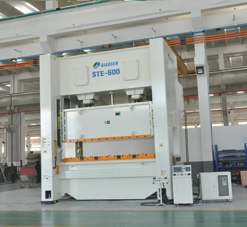
H Frame Double Crank Press
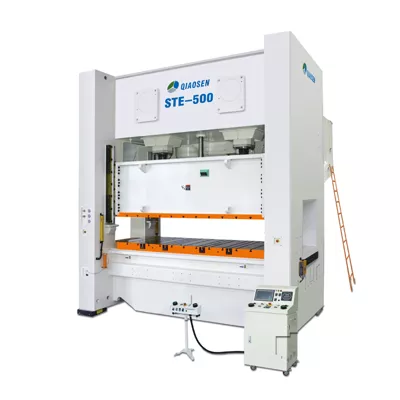
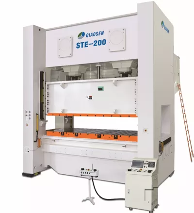
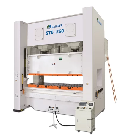
Basic Attributes
- Model STE500
- Press Capacity 80-800 ton
- Stroke Length 100-300 mm
- Drive System Siemens Motor
- Control System Siemens PLC
- Press Speed 15-120 S.P.M.
- Press Type H Frame Double Crank Pneumatic Press
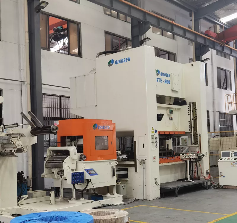
H frame crank press machine
JIS 1 inspection standard, high precision with thin oil lubrication device
Drawing

Specification
| Model | STE-80s | STE-80h | STE-110s | STE-110h | STE-160s | STE-160h | STE-200s | STE-200h | STE-250s | STE-250h | ||
| Punching Capacity | Tons | 80 | 80 | 110 | 110 | 160 | 160 | 200 | 200 | 250 | 250 | |
| Ability Occurence Point | mm | 4 | 2 | 6 | 3 | 6 | 3 | 6 | 3 | 7 | 3 | |
| Slider Strokes Per Minute | S.P.M | 45-90 | 80-120 | 40-70 | 60-90 | 30-55 | 40-85 | 20-50 | 35-70 | 20-40 | 30-60 | |
| Long Slider Length | mm | 150 | 100 | 180 | 120 | 180 | 130 | 250 | 150 | 280 | 180 | |
| Max Mould Height | mm | 380 | 330 | 420 | 370 | 450 | 400 | 500 | 450 | 550 | 450 | |
| Slider Adjustment Amount | mm | 80 | 80 | 80 | 80 | 100 | 100 | 120 | 120 | 120 | 120 | |
| Up Platform Area | mm | 1200×520 | 1200×520 | 1400×580 | 1400×580 | 1600×650 | 1600×650 | 1850×750 | 1850×750 | 2100×900 | 2100×900 | |
| Down Platform Area | mm | 1400×620 | 1400×620 | 1600×700 | 1600×700 | 1800×760 | 1800×760 | 2200×940 | 2200×940 | 2500×1000 | 2500×1000 | |
| Main Motor Power | kW×P | 7.5x4 | 7.5x4 | 11x4 | 11x4 | 15x4 | 15x4 | 18.5×4 | 18.5×4 | 22×4 | 22×4 | |
| Air Pressure | kg/c㎡ | 6 | 6 | 6 | 6 | 6 | 6 | 6 | 6 | 6 | 6 | |
| Model | STE-300s | STE-300h | STE-400s | STE-400h | STE-500s | STE-500h | STE-600s | STE-600h | STE-800s | STE-800h | ||
| Punching Capacity | Tons | 300 | 300 | 400 | 400 | 500 | 500 | 600 | 600 | 800 | 800 | |
| Ability Occurence Point | mm | 7 | 3 | 7 | 3 | 8 | 5 | 10 | 5 | 12 | 6 | |
| Slider Strokes Per Minute | S.P.M | 20-40 | 30-60 | 20-40 | 30-60 | 20-40 | 25-50 | 20-30 | 25-45 | 15-30 | 20-35 | |
| Long Slider Length | mm | 300 | 180 | 300 | 180 | 300 | 180 | 300 | 180 | 300 | 180 | |
| Max Mould Height | mm | 550 | 450 | 550 | 450 | 600 | 500 | 600 | 500 | 800 | 700 | |
| Slider Adjustment Amount | mm | 120 | 120 | 120 | 120 | 150 | 150 | 150 | 150 | 200 | 200 | |
| Up Platform Area | mm | 2100×900 | 2100×900 | 2200×900 | 2200×900 | 2500×1000 | 2500×1000 | 2800×1200 | 2800×1200 | 3400×1400 | 3400×1400 | |
| Down Platform Area | mm | 2500×1000 | 2500×1000 | 2500×1000 | 2500×1000 | 2800×1100 | 2800×1100 | 3000×1200 | 3000×1200 | 3600×1400 | 3600×1400 | |
| Main Motor Power | kW×P | 30×4 | 30×4 | 37×4 | 37×4 | 45×4 | 45×4 | 55×4 | 55×4 | 75×4 | 75×4 | |
| Air Pressure | kg/c㎡ | 6 | 6 | 6 | 6 | 6 | 6 | 6 | 6 | 6 | 6 | |
Benefits and Features
1. High-strength fuselage structure
The four-cornered-eight-surface guide rail used in punch press sliders offers several advantages, namely strong resistance to bias load and long-lasting precision retention. The efficiency and accuracy of the punch press heavily depend on the slider's performance.
The four-cornered-eight-surface guide rail is designed to enhance the stability and precision of the punch press slider. Compared to other guide rail types, such as the round-column guide rail, it offers superior resistance to bias load. This means that the slider can withstand external forces that may cause tilting or misalignment, ensuring consistent and accurate performance. Furthermore, the four-cornered-eight-surface guide rail provides a long-lasting precision retention. This means that even after extensive use, the slider can maintain its accuracy over an extended period. This is crucial in industries where precision and repeatability are paramount, such as automotive or aerospace manufacturing.
2. Thin oil lubrication system
The forced thin oil lubrication system is adopted to ensure the lubrication of the guide path. The number of presses can be increased by increasing the amount of oil (about 20%), and there is no need to refuel regularly, and the butter of the machine can be recycled.
3. Safety
Firstly, hydraulic overload protection devices are crucial components installed in punch press machines. These devices monitor the force exerted by the punch and die set-up during operation. If the force exceeds a predefined limit, the hydraulic overload protection device automatically limits the pressure, preventing any potential damage to the machine or injury to the operator. This device acts as a safety net, ensuring that the punch press operates within safe parameters.
Secondly, emergency buttons are strategically placed within easy reach of the machine operator. In case of an emergency or any unforeseen circumstances, pressing the emergency button immediately stops the operation of the punch press. This enables the operator to halt the machine quickly, reducing the risk of accidents or injuries. The placement and clear visibility of emergency buttons allow for a rapid response to potential safety hazards.
Lastly, light curtains are another safety feature utilized in the configuration of punch press machines. These curtains consist of a set of infrared sensors that create a protective barrier around the work area of the press. When the light curtain is interrupted by any object or body part, it sends a signal to stop the machine before any harm can be done. Light curtains provide a non-contact safety solution, allowing for continuous operation while ensuring the operator's safety.
4. Accessories
| No. | Parts name | Manufacturer/ brand |
| 1 | Main motor | Siemens |
| 2 | Slide adjustment motor | Sanmen/Teco |
| 3 | PLC | Japan Omron/Siemens |
| 4 | AC cont actor | French Schneider |
| 5 | Intermediate relay | French Schneider |
| 6 | Wet clutch brake | Yangyue/JieKai/ Italy OMPI/Self-produce |
| 7 | Double solenoid valve | TOYOOKI/America ROSS |
| 8 | Thermal relay, auxiliary connector | French Schneider |
| 9 | Control button | Japan IDEC |
| 10 | Two-piece and air filter pressure reducing valve | Air TAC |
| 11 | Lubricator | Air TAC |
| 12 | Pressure reducing valve | Air TAC |
| 13 | Hydraulic overload pump | Yuken/Japan Showa |
| 14 | Two hands button | Japan Fuji |
| 15 | Electric thin oil circulating lubrication device | Bijur/Liubian |
| 16 | Electric lubricating oil pump | Bijur |
| 17 | Main bearing | NSK//NTNTimken/TWB/Hawalow |
| 18 | Shockproof feet | Hengrun |
| 19 | air switch | French Schneider |
| 20 | Frequency converter | Sinee/Inovance |
| 21 | Photoelectric protection device | Sick/Lane |
| 22 | Touch screen | MCGS/Flexem |
| 23 | Seals | Japan NOK/TaiWan SOG |
| 24 | Preset counter | Japan Omron |
| 25 | Multi-stage switch | Siemens |
| 26 | Air blowing device | Air TAC/Japan SMC |
| 27 | Mould lighting | Puju LED |
| 28 | Mis-feed detection interface reserved | Wiring via PLC |
Configuration
| Oil pressure overload protection device | Pneumatic mold pad device |
| Slider adjusting device | Feeding device on the upper part of the slider |
| Digital die height indicator | Foot switch |
| Slider and die blance device | Safety block and safety plug |
| Counter | Quick die change device |
| Air source connector | Feeder machine |
| Rotary cam switch | Electric oil lubricating device |
| Crankshaft angle indicator | High performance dry clutch |
| Secondary fall protection device | Material rack |
| Air blowing device | Straightening machine |
| Mechanical anti-vibration feet | Manipulator |
| Reserved interface for misfeed detection device | |
| Main motor reversing device | |
| Photoelectric safety protection device | |
| Invertor | |
| Electric oil lubrication device | |
| Die lighting device | |
| Touch screen control device | |
| Slider 4 corners and 8 sides guide rail | |
| Wet clutch | |
| Mobile electric cabinet | |
| Mobile console |


